Technical Challenge
The computational modeling of MEMS (microelectromechanical systems) devices presents several interesting challenges.
Electrostatic actuators are nonlinear and frequently involve hundreds or thousands of individual comb elements. In many cases it is desirable to build simplified models of the devices that do not require the electrostatic fields to be resolved around every comb in the device.
In this example we address the challenges inherent in these simulations in a MEMS LiDAR mirror design. LiDAR (Light Detection and Ranging) devices are currently being developed by several companies to assist autonomous vehicles of various types: from self-driving cars to drones. The LiDAR mirror is used to scan a laser beam over a scene. The system detects reflections from objects in the scene and produces a 3-dimensional map of the space around the device.
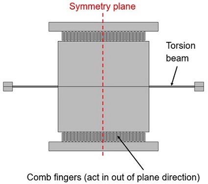
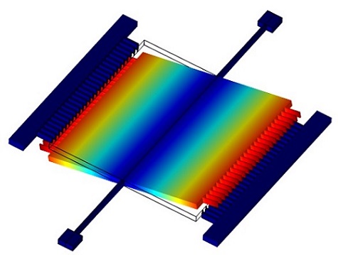
Figure 1. MEMS LiDAR mirror: The mirror is designed to twist about the axis of the torsional spring, with the comb drives actuating the structure in the out-of-plane direction.
Veryst Solution
Veryst developed a mixed analytic/finite element analysis (FEA) approach to analyze the structure in a scalable manner that can be applied to MEMS devices with several thousand combs.
Figure 1 shows how the MEMS mirror rotates about the axis of the torsional spring, driven by the out-of-plane motion of the comb drives.
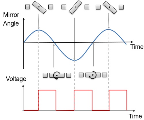
As shown in Figure 2, the angular frequency of rotation is half that of the actuation frequency. Electrostatic actuators always produce attractive forces, so the actuators are only switched on during those parts of the cycle when the mirror is moving towards zero angle.
MEMS simulation tools that explicitly solve the coupled electrostatics and mechanical problems at a single frequency could not simulate this device, since there are two frequencies involved in the problem.
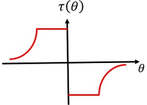
Considering the problem analytically enables us to model it numerically more efficiently. By neglecting the fringing fields, it is possible to derive a closed form analytic expression for the comb capacitance (C) as a function of angle (θ). The torque (τ) on the system can then be derived from the equation:
where V is the voltage applied to the combs.
The torque as a function of angle obtained from this approach is illustrated in Figure 3. The torque of the combs varies with angle as the combs disengage. Furthermore, the variation of the torque with time is periodic, and occurs at the same frequency as the mirror rotation.
We can model the system response by extracting the first term in the Fourier series representation of the torque, and then applying the torque to a frequency domain, finite element model of the structure.
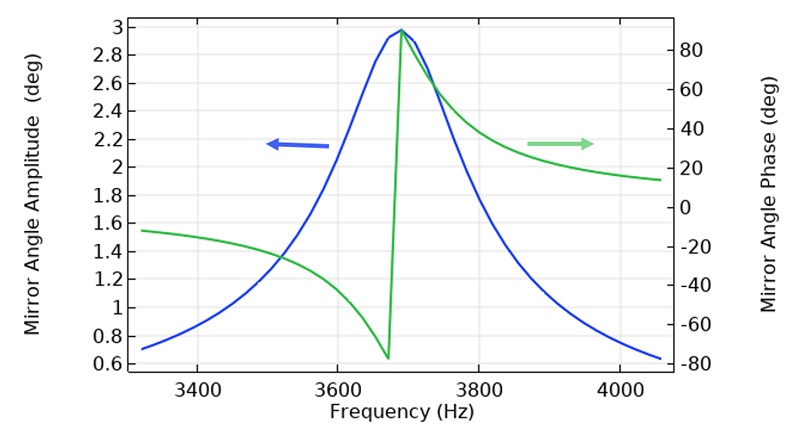
Finally, we can refine the analytic approximation to the capacitance by a separate model that explicitly computes the capacitance as a function of the rotation of the mirror. Using this approach allows tuning of the analytic model to account for fringing fields, resulting in an accurate model of the device. Additionally, heuristic or physics-based damping can be added to the model, to build a very accurate model of the system. The frequency domain response of the comb is illustrated in Figure 4, with heuristic Rayleigh damping added to the system with a Q of 70.
This approach can be applied to much larger MEMS devices with several thousand combs. It is possible to build finite element system models of large MEMS devices, such as multi-axis gyroscopes, by using analytic forces with fringing factors derived from detailed simulations of the capacitance-voltage characteristics of individual comb banks.
In addition to the simulations that we discuss in detail here, Veryst also has expertise in the area of MEMS design for reliability.
In this example, we could consider the design reliability as a function of frequency and torque, to ensure that the mirror lifetime will be sufficient for the application. We apply our extensive knowledge of MEMS device failure mechanisms in use conditions during simulation evaluation.
Failure mechanisms for the LiDAR mirror in this study also include:
- Mirror metal diffusion resulting in reflectivity reduction at elevated temperature
- Electrostatic discharge damage to the MEMS structure
- Fracture upon experiencing mechanical shock and/or drop
- Particle movement resulting in mechanical obstruction
Veryst also provides reliability test plans. Please contact us to learn more.