Technical Challenge
Many real-world structures contain thin conducting or insulating layers that are difficult to represent as a three-dimensional domain in an electromagnetic simulation. Structures with very high aspect ratios present significant challenges in electromagnetic simulations, resulting in difficulties with meshing and an ill-conditioned system matrix due to high aspect ratio elements. Instead of modeling thin structures as solid domains, it is desirable to represent them as shells.
COMSOL Multiphysics® contains a shell feature (the “Transition Boundary Condition” feature) that allows the modeling of a single layer shell – however it does not support multi-layer shells. Therefore, Veryst needed to modify the existing feature to allow for multi-layered shells to be included in a simulation.
Veryst Solution
We implemented an equation-based multi-layer shell in COMSOL Multiphysics®, based on the literature1. This enabled the simulation of stacks of insulating and/or conducting layers in an electromagnetic simulation. Veryst used COMSOL’s Physics Interface Builder to streamline the development of the custom equations needed to implement multi-layer shells, allowing us to assemble a complex system of equations accurately in just a few hours. Figure 1 shows some of the expressions we developed and the corresponding equations that we implemented for a two-layer shell.
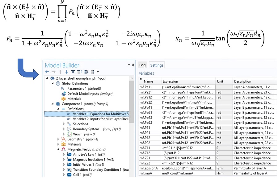
Figure 2 shows the magnetic field around an 80-turn square cross-section coil, which is excited with 100 mA of current at 100 kHz. The resulting magnetic field induces currents in a conducting loop (O.D. 2 mm) consisting of 5 μm of copper on 20 μm of titanium. These layer thicknesses are small compared to the other dimensions in the model and are best represented as a shell. To validate the shell implementation, we created an additional model in which the thin layers are represented as domains. Figure 2 shows a comparison of the induced current in the shell with the equivalent 3D model.
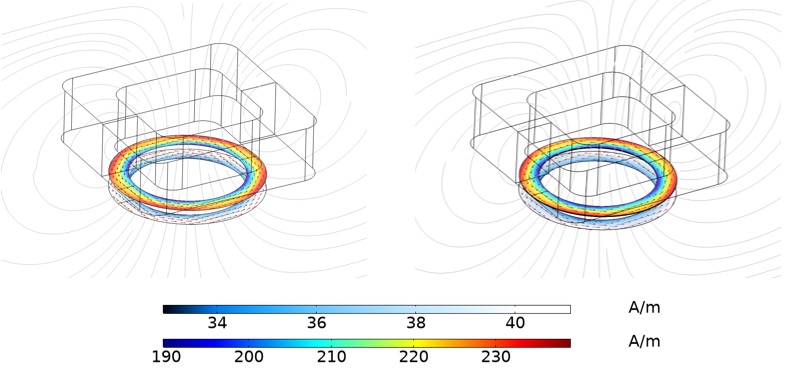
The agreement between the shell model and the explicit domain representation is excellent. For larger aspect ratios or more layers of the thin structure, meshing the thickness of the structure becomes impractical, and it is necessary to use the shell.
This implementation of thin shells can be used for low and high frequency electromagnetic simulations in the frequency domain. In this case it was implemented in COMSOL’s Magnetic Fields interface.
1 “Approximate Boundary Conditions for Thin Structures,” Anders Karlsson, IEEE Transactions on Antennas and Propagation, Vol. 57, no. 1, pp. 144-148 (2009).
2 For the equations in Figure 1, ET+/- and HT+/- are the tangential electric field and magnetic field strength, respectively, above (+) or below (-) the shell; n is the unit normal to the shell (pointing in the + direction) and ω is the frequency of excitation. Each layer is assumed to have complex permittivity εn, complex permeability µn and thickness dn. Note that we did not implement the finite thickness corrections discussed in Karlsson’s paper, although the extension is straightforward.