Technical Challenge
Eddy current-based axial magnetic couplings (ECAMCs) consist of two opposing discs, one typically made of a conductive material and the other embedded with permanent magnets. The magnets are arranged with alternating north and south poles, creating an axial flux path. As the drive rotates, the changing magnetic field induces eddy currents in the conductive disc, generating a secondary magnetic field that interacts with the primary magnetic field, allowing torque transfer without mechanical contact. These couplings are well-suited for applications requiring smooth, non-contact torque transmission - such as in vibration-sensitive systems, precision machinery, and speed-controlled devices - offering the
added benefits of inherent torque limiting, reduced electromagnetic interference, and improved thermal tolerance compared to their permanent magnet counterparts.
The torque transmitted by ECAMCs is influenced by several factors, including the conductivity and thickness of the conductive disc, the strength and orientation of the magnets, the air gap between the discs, and the rotational speed of the driver. The interplay between induced eddy currents, material properties, and geometric factors introduces significant complexity. This requires the use of numerical methods such as finite element analysis (FEA) to optimize performance and ensure efficient torque transmission across varying operating conditions.
Veryst Solution
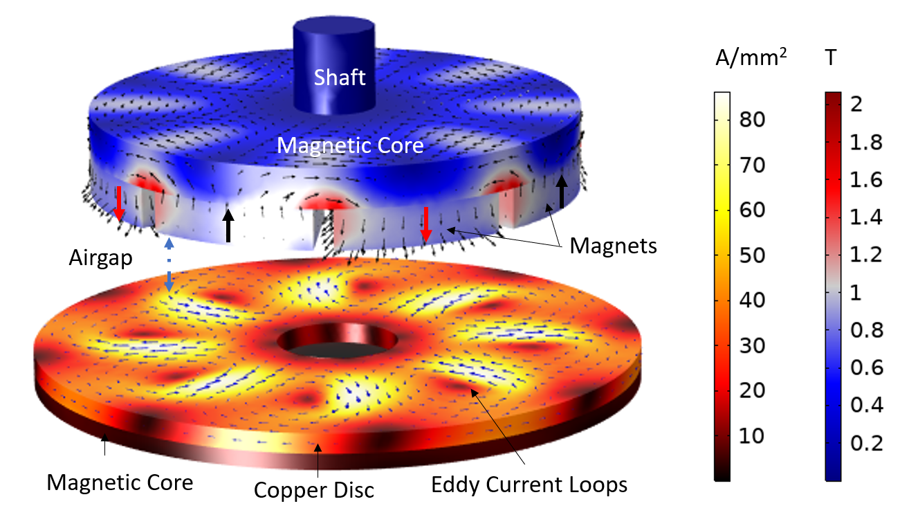
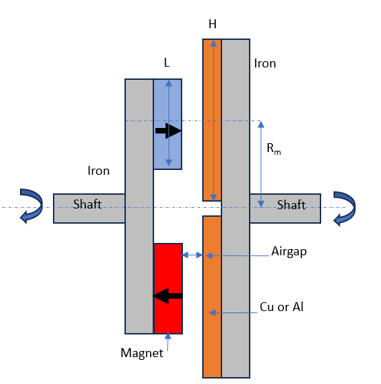
Veryst used COMSOL Multiphysics® to simulate the electromagnetics performance of the ECAMC to optimize transmitted torque and evaluate the operational range. The example model presented here is based on an experimental design from the literature [1], which is shown in Figure 1.
The magnetic flux density on the top drive disc and the eddy current induced on the bottom follower disc at 1,000 RPM for a four-pole pair configuration show the generation of eight eddy current loops.
.
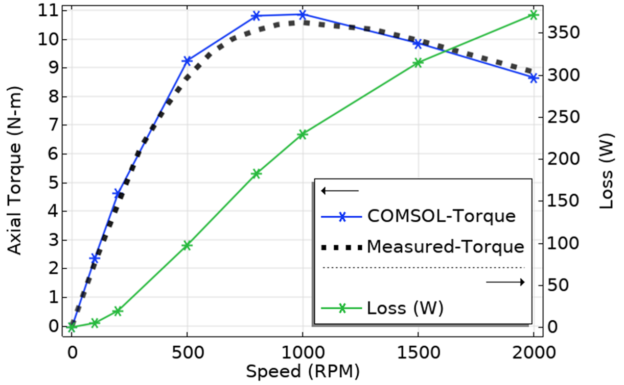
We calculated the torque-speed relationship and compared the results with the experimental data from the reference1 for a five-pole pair configuration with a 7 mm air gap, as shown in Figure 2. The simulated torque closely aligns with the experimental data, validating the model's accuracy and reliability. The torque increases steadily up to around 1,000 RPM, after which it begins to decline as speed increases further. This decline is attributed to increased losses at higher speeds. Therefore, this design is ideal for operation around 1,000 RPM.
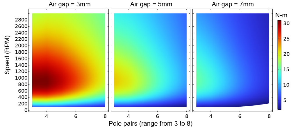
Next we investigated how two key design parameters - the number of pole pairs and the air gap - affect electromagnetic torque transfer. As illustrated in Figure 3, the maximum torque is achieved with fewer pole pairs and a minimal air gap, highlighting the optimal coupling configuration. However, practical considerations such as installation constraints or operational misalignments may require larger air gaps. In such cases, torque can decrease considerably as both the air gap and the number of pole pairs increase, making it essential to assess the device's performance across its full operational range.
We next assess the impact of rotor misalignments in both axial and angular directions. Our findings show that with up to 5 mm of axial offset between the two discs, the peak torque transmission is decreased by only 1.6%. Conversely, rotational misalignment has the opposite effect, increasing the peak torque by 4.5% for a 1.5° rotational offset.
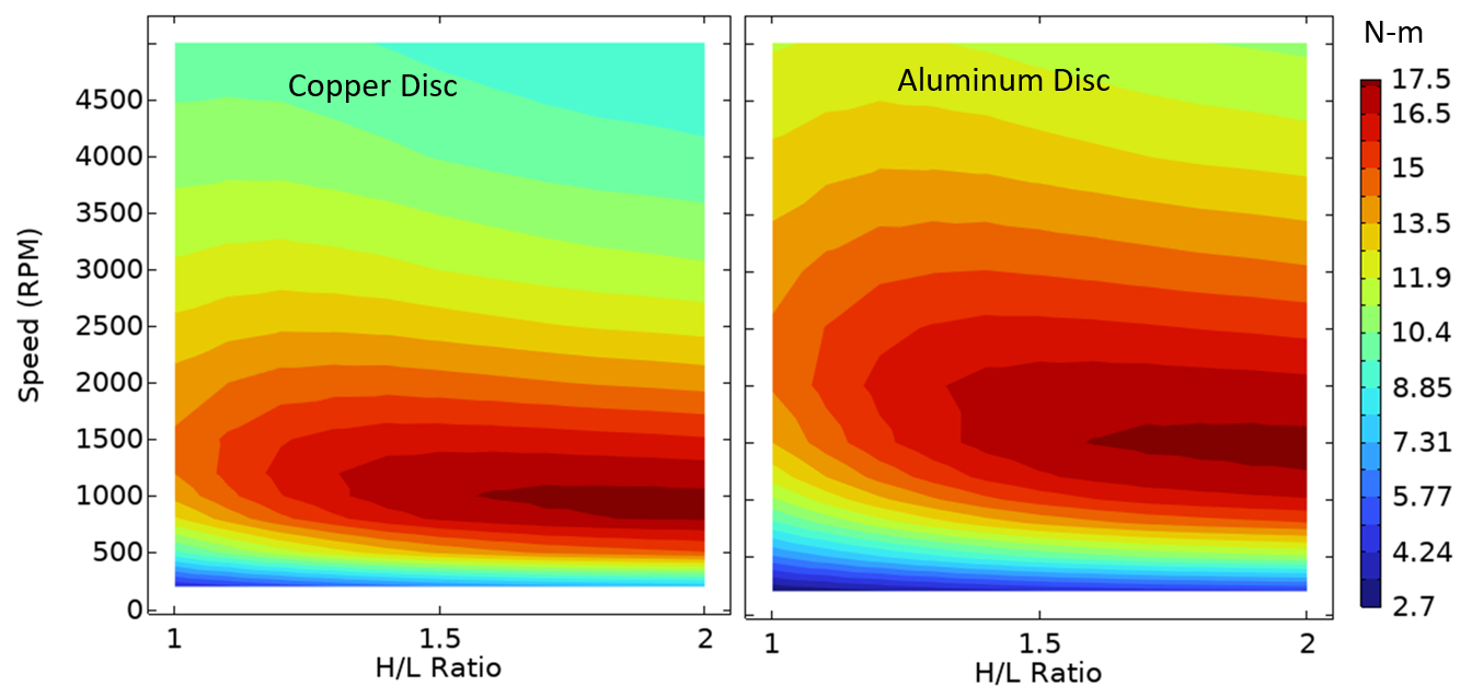
Finally, we performed a parametric sweep to investigate the effect of torque production for critical geometric parameters at varying speeds. As shown in Figure 4, we define H as the radial length of conductive material and L as the radial length of the magnet. We fix L at 30 mm and vary H from 30 mm to 60 mm, resulting in the ratio H/L varying from 1 to 2. The surface plot of torque as a function of RPM and H/L ratio is shown for both copper and aluminum discs in Figure 5. We found that the peak torque occurs at around 1,000 RPM for copper and at around 1,500 RPM for aluminum. A higher H/L ratio is preferred for optimal design. The lower RPM value for peak torque in copper is attributed to greater losses in the copper design.
Conclusion
Eddy current-based actual magnetic couplings provide a reliable, contactless solution for smooth torque transfer, especially in systems where minimizing wear and vibration is critical. These couplings offer flexibility in design, allowing for the customization of performance by adjusting parameters such as air gap, size, material, conductivity
and magnet configuration. By leveraging advanced simulations and modeling, the design can be optimized to meet the specific operation demands of various applications, insuring efficient, low-maintenance torque transmission across a wide range of industrial environments.
Reference:
"Three -dimensional Analytical Model for Axial-Flux Eddy-Current Couplings and Brakes under Steady-State Conditions," T. Lubin, A. Ressoug. IEEE Transactions on Magnetics, Institute of Electrical and Electronics Engineers (IEEE), Vol. 51, Issue 10, PP. 1-12, 2015.