Technical Challenge
Accurate simulation of hot forging includes the choice of a metal constitutive model for the deformation of the work piece. Veryst was asked to investigate the role of material modeling on the accuracy of a forging simulation.
Veryst Solution
Veryst implemented a rate-independent elastic-plastic material model and a more sophisticated rate-dependent internal variable material model (Anand, International Journal of Plasticity, 1989).
Veryst then analyzed the performance of these constitutive models in simulations of hot forging operations by comparing the stresses in the workpieces to determine whether the constitutive model assumptions changed the results of the simulations in any significant way.
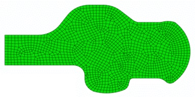
Original Preform Geometry
Figure 1 shows the cross-section and finite element mesh of the axisymmetric forging preform.
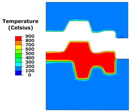
The finite element analysis included the forging dies and heat transfer between the preheated workpiece and cooler dies.
Figure 2 shows the workpiece and die temperatures at the end of the forging pass.
There is obvious cooling of the workpiece surface given interaction with the die, which will affect forging die force, stresses within the workpiece, and the resulting deformation strain field.
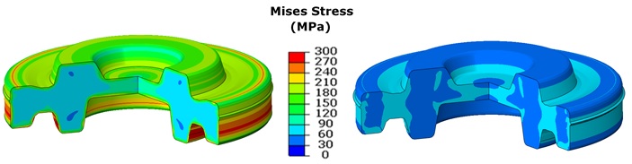
Comparison of Maximum von Mises Stresses
Figure 3 shows the von Mises stress fields at the end of the forging pass. Von Mises stresses are higher on the surface of the workpiece with the Anand material model (left) compared to the workpiece with the elastic-plastic material model (right). The Anand material model includes both temperature and rate dependence, whereas the elastic plastic model does not.
Workpiece cooling with the Anand model effectively stiffens the metal near the workpiece surface, which in turn results in increased stresses. Furthermore, the distribution of stresses is not the same in these models. We do not observe peak stresses in the same locations in these models. The strain distributions within the two workpieces are also different.
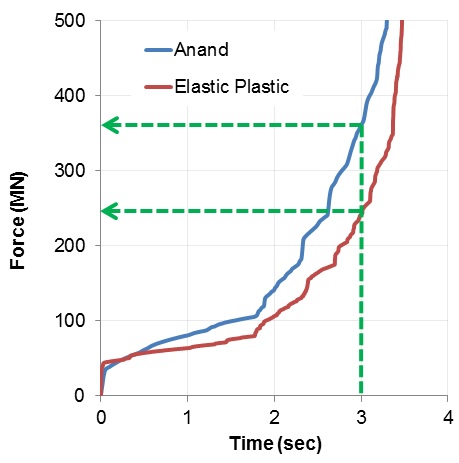
Force vs. Time
Figure 4 provides the die force predicted from the two analyses. The rate-dependent material model predicts a significantly larger die force throughout the forging pass. These results are affected by calibration of the selected material models to the stress/strain data for the workpiece alloy.
An accurate simulation therefore also depends on the quality of test data and calibration of that data to an appropriate material model.