Technical Challenge
Finite element analysis can be extraordinarily useful to manufacturers who conduct polymer forming operations. The ability to predict the final shape of a part and the stress and strain state in the material prior to tooling helps prevent tearing, unexpected material flow, and other polymer failure mechanisms. In a process similar to that applied to metal forming, iterating designs through simulation optimizes tooling while reducing development time.
While the benefits are great, polymer forming presents challenges to simulation beyond those associated with metals. Often the forming process involves both contact and large material deformations, both of which make it difficult to converge on an accurate solution. While this kind of simulation is common for metals, engineers may have less confidence in the results when it comes to polymers.
Polymers are often highly temperature- and rate-dependent, exhibiting significant stress-relaxation, creep and recovery, and exaggerated forming-induced anisotropy. Despite these challenges, the technology to model polymers accurately exists, even under large deformations.
Veryst Solution
Veryst used a tube joining case to examine the steps required to produce an accurate model of an example polymer, polyether ether ketone (PEEK), and show the consequences of oversimplification.
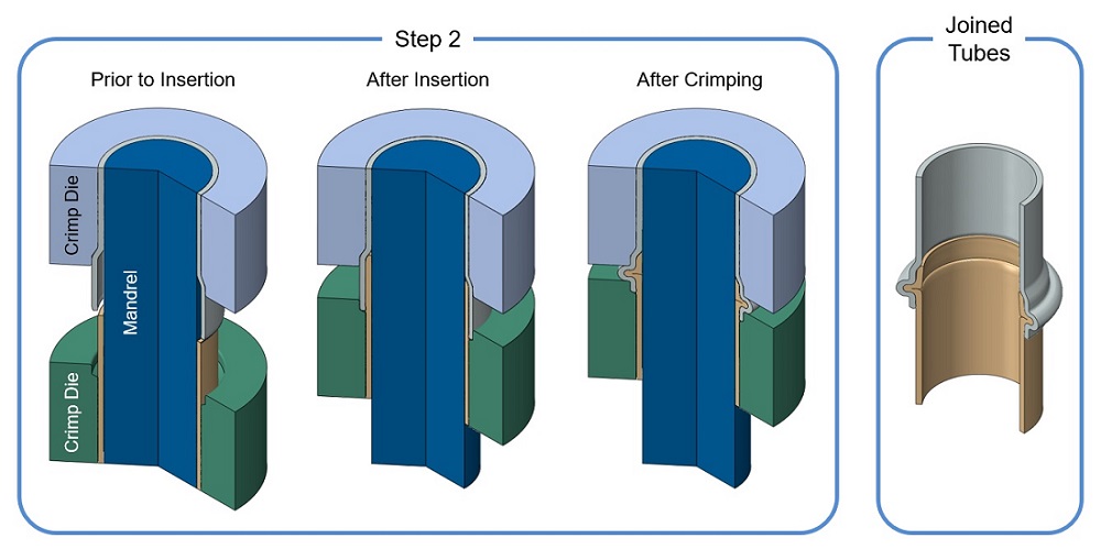
The approach to tube joining used here involved a method1 for joining polymer and metal tubes that can be performed at room temperature. The forming operation crimps together the two tubes in a two-step process. Figures 1 and 2 show a representation of the process.
Figure 1. The tubes begin at the same diameter. In step one, part of the metal tube is expanded so that the plastic tube fits inside. This is done with an expansion punch that is forced into the metal tube, which is held in place by a corresponding expansion die.
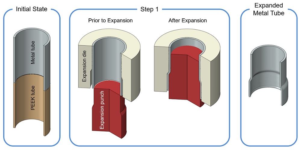
Figure 2. In step two, the plastic tube is inserted into the expanded metal tube and the two are crimped together. After insertion, the die holding the plastic tube now fits closely around the end of the metal tube. The dies holding both tubes are forced together, buckling the tubes simultaneously. A mandrel located inside the tubes ensures that they buckle outwards. The dies come together just enough to crimp the joint, ensuring good contact pressure between the metal and plastic.
Before sending the tooling to the machine shop, we wanted to simulate our proposed tooling design and iterate if necessary. This forming operation produces large deformations in both the metal and PEEK, so Veryst needed accurate material models for both that could handle large strains.
For the metal we used an elastic-plastic material model with isotropic hardening, which we defined based on large strain tensile tests of the material. Since the stress-strain behavior of polymers is often rate dependent and asymmetric in compression and tension, we performed several tests on the PEEK.
Testing
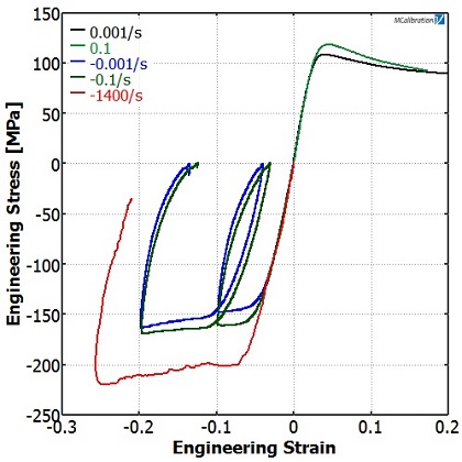
We performed uniaxial tension and compression tests at different strain rates.
When we plotted the results together (Figure 3) we could clearly see the strain rate dependence of the material.
These test results informed us that we should choose a rate-dependent plasticity material model.
Material Model Calibration
Engineers can choose from hundreds of material models, but taking the time to choose the right one is important for good simulation accuracy.
Veryst examined two material models of varying degrees of sophistication and compared (a) how well they predicted the data, (b) how well they validated, and (c) how they differed in their predictions.
The Johnson-Cook (JC) rate-dependent plasticity model is common and relatively easy to use. It has few parameters, making calibration very efficient.
Figure 4 shows a best fit calibration to the PEEK test data, obtained using the material model parameter fitting feature found in the test analysis software MCalibration®, originally developed by Veryst and now available through PolymerFEM.com.
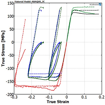
Note that the yield stress of the PEEK in compression is not the same as in tension — a feature that the JC model cannot resolve. If we want to be accurate in both loading modes, we have to pick a compromise fit that slightly underpredicts the compressive yield stress but overpredicts the tensile yield stress.
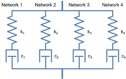
For comparison, we also considered a more complicated material model: the Flow Evolution Networks (FEN) model. The FEN model was built for polymers and has significantly more material parameters. The FEN model can be represented by four parallel networks, as shown in Figure 5.
Each network consists of the micro-mechanism inspired 8-chain hyperelastic spring, in series with a nonlinear viscoplastic dashpot.
With 31 parameters, it is much harder to calibrate manually.
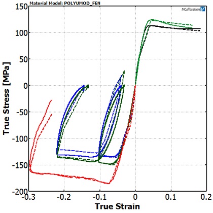
Again using MCalibration software, we let the computer perform multiple optimization analyses to arrive at a best fit (Figure 6).
The FEN model can accurately capture the asymmetry between tension and compression, the rate-dependence, and the unloading of the material.
Material Model Validation
We used validation experiments to test the robustness of the material model. Validation experiments should be tailored to mimic the loading conditions in the real application. They do not need to look precisely like the part being designed, but should subject the material to a stress state that goes beyond what was tested for calibration
We performed the small punch test and an impact test to validate these PEEK models. The combination of these experiments tested the models over multiaxial stress states that are dominant in both tension (small punch) and compression (impact), as well as over a large range of strain rates.
Small Punch Test
In the small punch test, a hemispherical-tipped rod pushes into a disk of the material. The force is measured as a function of the penetration distance. This test subjects the material to bending stresses and large biaxial tensile deformations.
Figure 7 shows the validation model for this experiment.
We simulated both the JC and FEN models in this way, which yielded the force-displacement curves shown in Figure 8.
Both models give a good representation of the actual PEEK punch test, but the FEN model performs slightly better. The JC model overestimates the tensile yield stress, resulting in a higher value of required forming force. It is also apparent that the JC model does not accurately capture the nonlinear unloading.
Impact Test
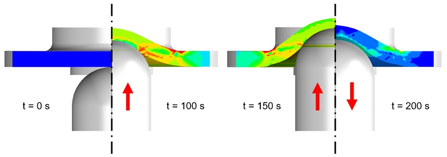
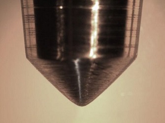
We performed the impact test using a rounded steel indenter dropped from roughly 2 meters above a flat PEEK specimen (see Figure 9).
The experiment was replicated using an axisymmetric model of the indenter and PEEK specimen (Figure 10).
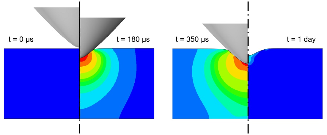
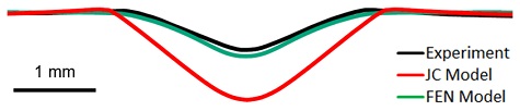
After the test, we sectioned the specimen and measured the profile of the resulting indentation. Figure 11 compares the two models against the measured profile.
The JC model seriously overpredicts the amount of permanent deformation. Two aspects of the JC model’s fit produce this lack of experimental agreement. First, we underestimated the compressive yield stress in order to gain a better prediction in tension and, second, the model is unable to predict the recovery of the material upon unloading. The FEN model on the other hand does an excellent job predicting the final deformation state.
Application
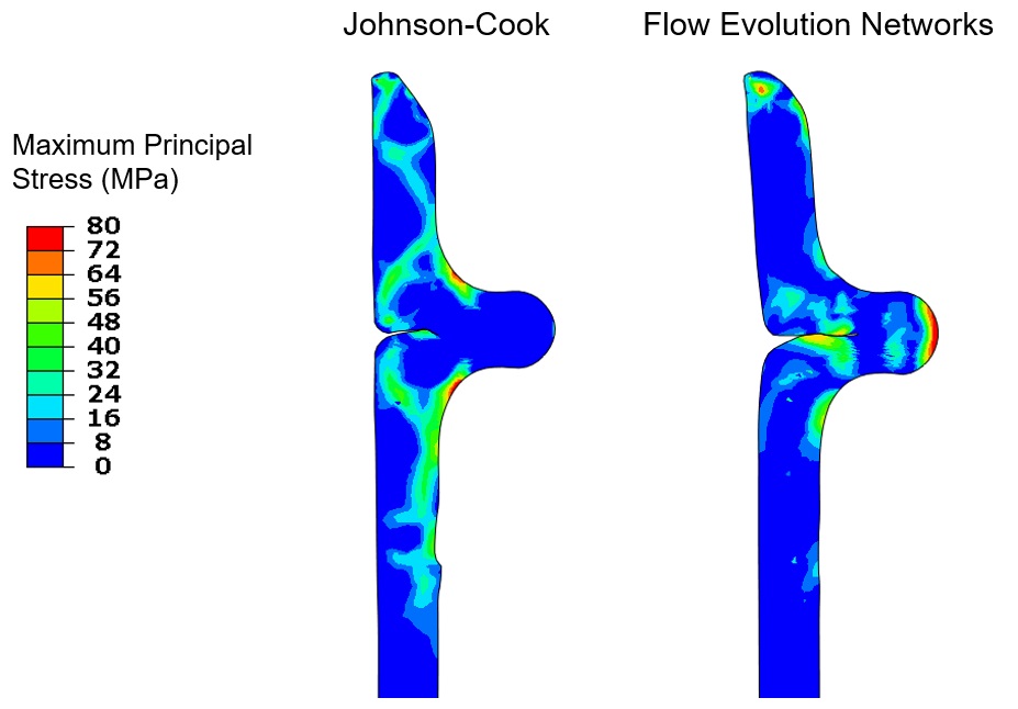
We could then take the calibrated material models and implement them in our manufacturing simulation. The JC and FEN material models produced similarly shaped profiles, but substantially different stress states. Figures 12 and 13 show the resulting tube profiles and the maximum principal stress in the PEEK after forming.
The locations of high residual stress are significantly different between the two material models.
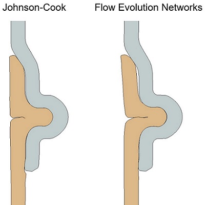
These stress fields (and associated strain fields) both identify potential failure locations and suggest die design changes. If we were using the JC model, we might try to reduce the stresses at the corners where they are highest. But since we know the FEN model is more accurate, we should focus on reducing the stress at the outside of the crimp.
Note how the simple process of material model selection dramatically changes subsequent forming design decisions.
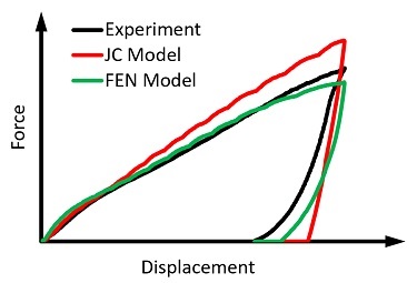
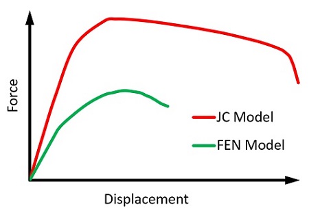
To illustrate further the effect of material model selection, suppose we wish to know the axial strength of the joint. After the forming process, we simulate pulling apart the joint. Depending on which model we use, we get a very different prediction of the failure load.
Figure 14 shows the force-displacement curves for both models.
The JC model predicts a peak force 80% larger than the force predicted by the FEN model. If we decided to use this overly simplified model, we might expect our part to meet a higher load performance specification. Using the more sophisticated FEN model, we have a more realistic expectation of the part’s performance.
Engineers may avoid large strain simulations of polymers. As we have illustrated, a simple error in material modeling gives drastically different results, justifying in part a reasonable cause to be wary of such simulations. However, proper validation experiments can assure confidence in the results.
Using the state of the art in material modeling along with rigorous testing and validation, high strain polymeric simulations can lead to realistic predictions.
1. Alves, L. M., C. M. A. Silva, and P. A. F. Martins. "Joining of polymer and metal tubes by cold forming." Proceedings of the Institution of Mechanical Engineers, Part L: Journal of Materials Design and Applications (2015): 1464420715605660.