Technical Challenge
Stent implantation is widely used as a minimally-invasive treatment for various artery diseases. Stents are open structures that provide support to blood vessels to ensure blood flow and are typically made of metal alloys and polymers. Absorbable polymers such as PLLA (poly-L-lactic acid) are beneficial due to their biodegradable characteristics and their higher long-term efficacy by preventing issues such as tissue inflammation and stent fracture. Stent manufacturers use computational modeling and simulation to predict device performance and deployment and to optimize their design, as well as providing evidence for safety and
efficacy of the devices. The credibility of simulations and models is critical because of the potential risk that an incorrect design decision from a simulation may ultimately pose to a patient. The United States Food and Drug Administration (FDA) require both verification of computational models as well as validation of medical device simulations with physical experiments, with published guidance to aid manufacturers and engineers.1 Accurate simulation of PLLA stent behavior is challenging and requires use of advanced material models that can capture the time-dependent response of the PLLA material.
Veryst Solution
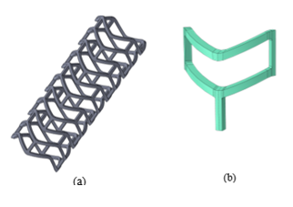
Veryst simulated crimping of a PLLA stent with a sample geometry using finite element (FE) analysis. We present the geometry of the stent as well as a quarter symmetry unit cell model used for the FE model in Figure 1.
During implantation, PLLA stents are crimped into a catheter and directed to the target location in a patient’s diseased artery. We simulate the crimping with contact between the stent and the catheter (not shown in Figure 1). We performed the crimp simulation with an implicit quasi-static scheme. First, we crimped the FE model of the stent to its final diameter and then we maintained the stent in that state to capture the stress relaxation caused by the viscoplastic behavior of the PLLA material.
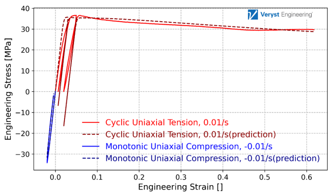
Veryst calibrated an Abaqus parallel rheological framework (PRF) model using Ansys’ MCalibration® tool to capture the plasticity and time-dependence properties of the PLLA material. We present the results for the material model calibration in Figure 2. The model matches the experimental data well, capturing the cyclic loading, and the model has a normalized mean absolute difference error of 5.2%.
Verification techniques are categorized into code and solution verification, and the latter is employed to ensure that the numerical solution has converged to the exact solution of the mathematical model. Veryst used the grid convergence index (GCI) method suggested by the American Society of Mechanical Engineers (ASME) VV-40 document for solution verification.2 This approach uses mesh refinement and Richardson extrapolation to estimate the exact solution and can be used as a post-processing technique after performing FEA to estimate any quantity of interest.
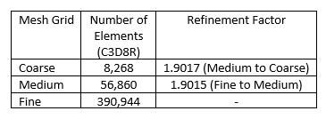
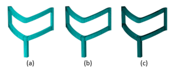
Veryst used three mesh configurations for this solution verification study. We used a constant refinement factor of r = 1.9 for this analysis, where refinement factor r is computed using the number of elements in each mesh as
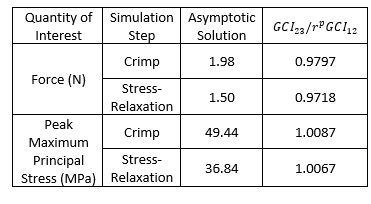
where Nn and Nn+1 are the number of elements in the relatively coarse and fine mesh; and D is the dimension of the mesh. A summary of mesh configuration information is presented in Table 1 and we show the mesh grid configurations for the three cases in Figure 3.
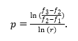
Based on this approach, we computed the grid convergence index (GCI) for each pair of mesh configurations3:
where F2 is a safety factor assumed as 1.25 when three or more meshes are considered, and
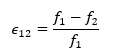
In which f1 and f2 correspond to solutions for coarse and medium mesh;
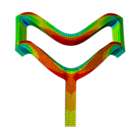
Veryst considered two quantities of interest for this solution verification analysis: the simulated force to impose the crimp deformation and the peak maximum principal stress resulting from the crimp. As an example, we show the maximum principal stress contour for a quarter-symmetry unit cell model of the PLLA stent with coarse mesh configuration in Figure 4.
The models are in the asymptotic range or verified if the ratio
Conclusion
Our results show that the GCI metric approaches 1 for a sequence of refined mesh configurations. This demonstrates a verified numerical solution for crimping of a PLLA stent modeled with an advanced viscoplastic material model using a method from ASME VV-40. This showcases the applicability of Veryst’s solution verification approach to polymeric materials, advanced material models, and the stent crimping simulations that are widely used in industry.
Link to VV-40 Document: VV40-Assessing Credibility of Computational Modeling through Verification and Validation Application to Medical Devices - ASME
Link to our paper: Solution Verification Study for Finite Element Analysis of PLLA Stent Implantation | VVS | ASME Digital Collection
Paper Reference: Osloub, E, & Teller, SS. "Solution Verification Study for Finite Element Analysis of PLLA Stent Implantation." Proceedings of the ASME 2024 Verification, Validation, and Uncertainty Quantification Symposium. ASME 2024 Verification, Validation, and Uncertainty Quantification Symposium. College Station, Texas, USA. May 15–17, 2024. V001T04A001. ASME. https://doi.org/10.1115/VVUQ2024-132962
References
[1] U.S. Food and Drug Administration, "Assessing the credibility of computational modeling and simulation in medical device submissions," Guidance for Industry and Food and Drug Administration Staff, 2023.
[2] ASME VV-40, "Assessing Credibility of Computational Modeling through Verification and Validation: Application to Medical Devices," American Society of Mechanical Engineers, New York, NY, 2018.
[3] W. Oberkampf and C. J. Roy, Verification and validation in scientific computing, Cambridge University Press, 2010.