Technical Challenge
The additive manufacturing (AM) industry is maturing at an exciting pace, and a wide variety of 3D-printing techniques, raw materials, and design tools are now available. To date, engineers have employed AM primarily for rapid prototyping. However, for those industries that can derive value from highly complex part geometries, the true goal remains to employ AM for the production of reliable end-use parts.
One of the challenges of designing with AM polymers is accounting for their anisotropic mechanical properties. These materials frequently fail more easily when loaded along the build direction due to weak interlayer bonding. An engineer could conservatively assume the weakest properties for every orientation, but this assumption counters the goal of using AM to enable highly-optimized part geometries. Therefore, maximizing AM part performance requires a detailed understanding of this mechanical anisotropy exhibited by AM polymers.
Veryst Solution
Veryst characterized the mechanical anisotropy of nylon processed by selective laser sintering (SLS). The mechanical properties of AM materials are often reported in only the 0° and 90° degree orientations. These data alone do not fully describe the material anisotropy.
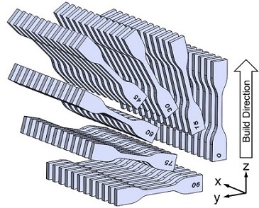
To build a complete description of how material properties depend upon the loading orientation with respect to the build direction, Veryst printed and tested tensile specimens at seven orientations, as shown in Figure 1.
Veryst used its ADMET load frame to test materials in tension to failure, and measured strain using full field digital image correlation (DIC). Figure 2 presents the stress-strain curves of the weakest and strongest specimens in the study alongside the ADMET test machine. The inset image shows a representative DIC strain field captured during the experiments. Interestingly, the material performed best when loaded at 60°, not 90°, with respect to the build direction.
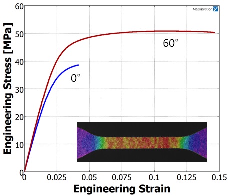
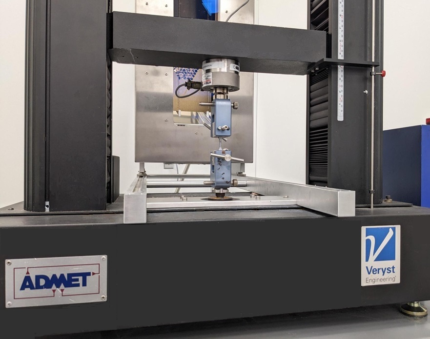
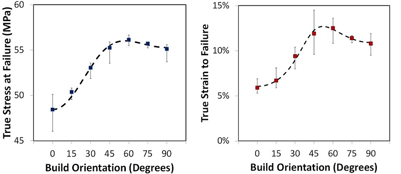
Figure 3 shows how the true stress and true strain at failure varied with build orientation. The points represent the mean measured values and the error bars denote the minimum and maximum measured values for nine tests. The trends in the data are well-captured by the models shown as dashed lines in Figure 3.
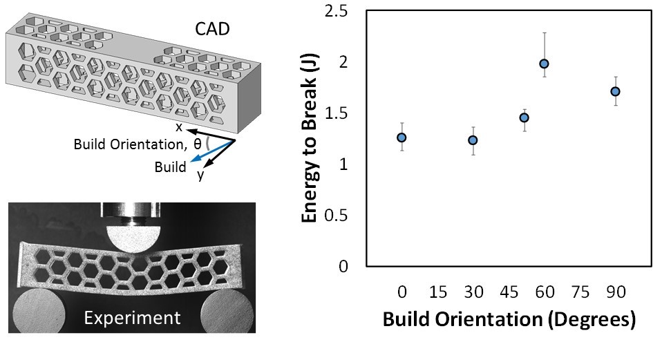
When possible, engineers should work to align the stresses in a part with the strongest material orientation. As an illustration of why this is important, Veryst printed a lattice structure in different orientations and loaded the parts to failure in three-point bending (Figure 4). Consistent with the tensile test data, the structural performance was maximized by printing the part such that the max principal stress was oriented ~60° to the build direction. By optimizing the build orientation, the energy required to break the part increased by 58% compared to the 0° orientation, and 16% compared to the 90° orientation.