Technical Challenge
Wear is the gradual removal of material from solid surfaces that are subjected to sliding frictional contact. It is a complex phenomenon that is relevant to many problems involving contact, such as mechanical brakes, seals, metal forming, and orthopedic implants. However, wear modeling is not directly available in most finite element codes.
Veryst Solution
Veryst implemented a wear model based on a modified version of Archard’s law—
ẇ = k(H,T)pNVT
—where the rate of change in wear depth ẇ at any point is related to the normal contact pressure pN, magnitude of sliding velocity VT, and a constant k that is a function of the material and temperature.
We implemented the wear equation at left in COMSOL Multiphysics using boundary ordinary differential equations (ODEs) with the wear depth as the independent variable. The wear depth is then used as an offset between the contacting surfaces. Contact is enforced only when the penetration between the contact surfaces is equal to the wear depth. This wear algorithm is very efficient but is only suitable for cases where wear is significantly less than the width of the contact surface.
Validation
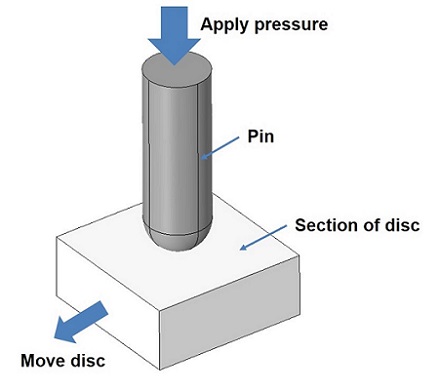
Among the tests we used to validate the wear model is the pin-on-disc wear test shown below. The disc is much stiffer and therefore wear occurs only in the pin.
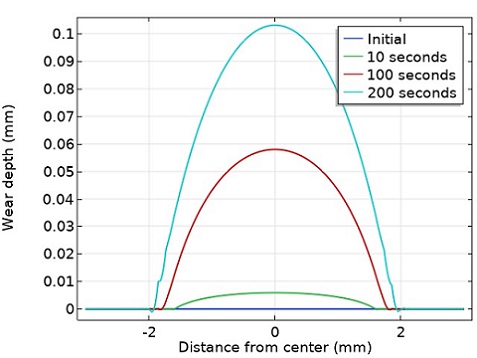
The graph in Figure 3 shows how the wear depth varies radially along the pin. The total volume loss, calculated as the integral of wear depth over the contact surface, was similar to the value calculated using Archard’s law, verifying the implementation of the wear model.
Application
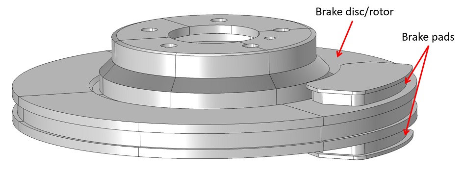
We used this wear model to simulate wear in disc brakes. We developed a 3D thermal-structural disc brake model involving representative brake disc/rotor and brake pads (see Figure 1). The structural and thermal processes are coupled through frictional heat generation, thermal expansion, and thermal contact. Both physics fields are also coupled to the wear depth evolution boundary ODE.
We did not explicitly model the rotation of the brake disc as we were not concerned with the transient structural behavior. Instead, the effects of the disc rotation were included as a convective term in the heat transfer analysis, in the velocity calculation for friction heat generation, in the calculation of friction conditions, and lastly in the wear equation.
The animation in Figure 4a shows the variation of wear depth with time due to a continuous braking pressure of 0.2 MPa applied to the backing plates. The results should be similar to a higher braking pressure applied intermittently over a short duty cycle (e.g. 0.4 MPa applied 50% of the time, with a cycle duration of 2 seconds). More complex realistic braking conditions can easily be examined as well. The wear is initially concentrated at the leading edge of the pad but gradually spreads out over the pad. The wear is also greater at the outer radius of the pad due to the higher tangential sliding velocity. This wear in turn decreases the contact pressure between the disc and pads as seen by the contact pressure animation in Figure 4b.
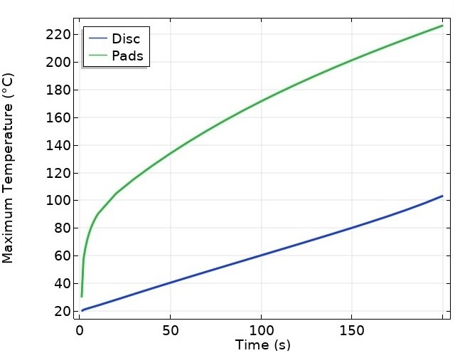
The temperature of both disc brake and pad increase over time due to frictional heat generation (Figures 5 and 6). The temperature rise for the pads is much higher than for the disk, as expected, and steady state temperature is not reached even at 200 seconds.
This model can be used to simulate the evolution of wear in other brake applications, as well as orthopedic products.