Technical Challenge
Thermal management is crucial to maintaining battery life and performance for medical devices, consumer products, automobiles, and grid power applications. During operation, batteries can generate significant heat that must be dissipated by passive or active methods. When high rates of heat dissipation are needed, active cooling methods such as liquid cooling or air exchange systems are employed, often in conjunction with passive methods such as heat sinks and thermal vias.
For such systems, the battery pack temperature depends on the rate of coolant flow, the battery load, and the thermal properties of all materials. Multiphysics simulation is an excellent tool to improve the design of thermal management systems, enabling fast, detailed, and accurate predictions of the temperature distribution and impact of design changes.
Veryst Solution
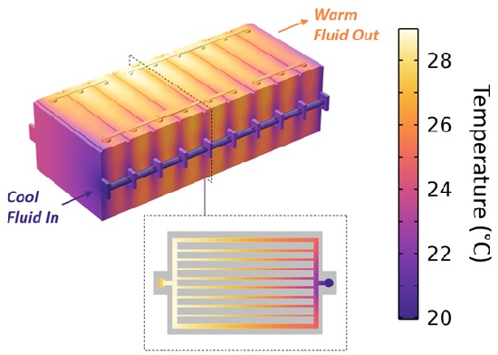
Veryst used COMSOL Multiphysics to simulate the coupled battery discharge, heat transfer, and coolant flow in cylindrical and prismatic battery packs with different thermal management configurations. Figure 1 shows the temperature distribution in a prismatic battery pack with liquid cooling.
In this particular configuration, the positive and negative terminals of the prismatic cells are both positioned on the top side. During discharge, the battery pack dissipates power as heat. To manage temperature gradients in the pack, the individual cells are separated by cold plates containing a network of parallel fluidic channels. Cool liquid injected on one side of the pack flows through fluidic channels, where it absorbs heat generated by the batteries and then exits on the opposite side at a warmer temperature.
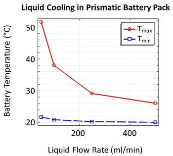
Increasing the coolant flow rate increases the rate of heat absorption, thereby reducing the temperature gradients in the battery pack. This is illustrated in Figure 2, where the maximum and minimum temperatures in the battery pack are plotted versus the liquid flow rate.
This plot shows the liquid flow rate necessary to maintain the battery cells below a threshold temperature, which is important for the longevity and performance of the battery pack.
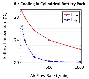
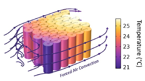
Other energy storage systems manage heat by using fans to blow air across the battery pack. Figure 3 shows a cylindrical battery pack cooled by forced air convection. Unlike most liquid coolants, air is a poor heat-transfer medium due to its low thermal conductivity and low heat capacity. Consequently, significant air flow is required to stabilize the temperature of a battery pack during discharge.
Figure 4 plots the maximum and minimum battery temperature versus the air flow rate. Note that the air flow rates required to stabilize the battery temperature are three orders of magnitude larger than in the liquid-cooled pack. Additionally, there is a large gradient in the temperature distribution of the individual batteries, meaning individual cell performance will vary throughout the pack.
Conclusion
Veryst used multiphysics simulations to predict the temperature distributions in two battery pack configurations with different coolants. Since pumping coolant requires power, there is generally a tradeoff between achieving fast cooling (requiring high coolant flow rates) at minimum cost (low flow rates) in both mobile and stationary power applications. Simulations such as the ones described here can be used to predict the amount of coolant flow needed to maintain battery cell temperature within the range for optimal performance, as well as optimize the design of the cooling system.