Technical Challenge
Micropumps play a key role in microfluidic lab-on-a-chip devices. Electroosmotic flow (EOF) pumps are micropumps with no moving parts based on electroosmosis, where motion of a liquid is induced by an applied external potential gradient. The electroosmotic effect can be described with the electric double layer (EDL) model developed by von Helmholtz (1879). Most surfaces, including silica, acquire a finite charge density when in contact with flow. The charged surface attracts counterions and repels coions. An electric field that is applied in parallel with the surface induces motion of the net charge in the EDL due to the Coulomb force in the direction of the electric field. The EDL pulls the charge-neutral bulk liquid by viscous drag and creates a new flow.
Electroosmotic flow pumps have several advantages compared with other micropumps. EOF pumps can create constant pulse-free flows without any moving parts. However, the main disadvantage of EOF pumps compared to conventional micropumps is the high voltage required to drive EOF pumps. In many microfluidic applications a flow rate of µL/s is needed. This can only be achieved by applying 1kV with a simple EOF pump, which is not practical.
Veryst Solution
A solution to the high voltage requirement of EOF pumps is a cascade pump system. Instead of a single electroosmotic pump, the cascade consists of several EOF pump stages in series, each with zero net voltage drop. Figure 1 shows a single stage (with two parts) in a cascade.
Using COMSOL Multiphysics, we analyzed a proof of concept of a single zero-voltage electroosmotic flow pump stage using CFD and analytical equivalent circuit theory. Figure 2 shows the velocity profile in the pump obtained from CFD simulation. The CFD model developed in COMSOL uses an electroosmotic boundary condition that applies velocity to the boundary based on Helmholtz-Smoluchowski relation:
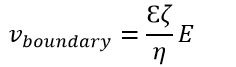
where E is electric field, ζ is zeta potential of channel wall, and η and Ɛ are viscosity and electric permittivity of the flow. Applying the velocity boundary condition is a reasonable simplification since thickness of the EDL is small, generally around a few nanometers.
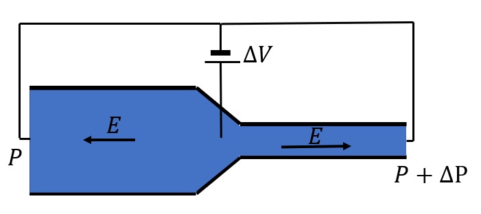
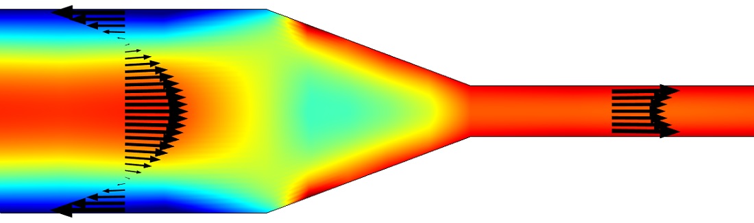
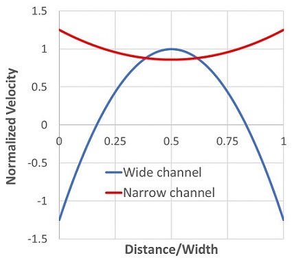
Figure 3 shows normalized velocity profiles.
Flow is unidirectional in the narrow channel and bidirectional in the wide channel. The electroosmotic flow in the narrow section acts as a high-pressure pump with forward electric field. The back pressure in the wide channel due to the reversed electric field is small compared to the small channel.
Therefore, while the accumulated voltage is zero, a net flow is maintained. This ensures EOF pumps use a low operating voltage that allows the pump to be operated with a battery and thus to be portable.
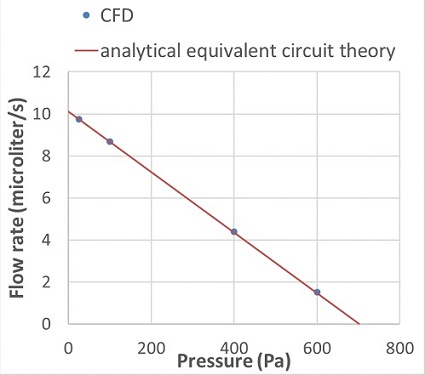
We used semi-analytical equivalent circuit theory involving hydraulic resistances, pressures, and flow rates to obtain the flow-rate-pressure characteristic Q-P for the single zero-voltage electroosmotic flow pump stage and compared it with CFD results.
The Q-P characteristic is found by noting that the flow rate in the two channels must be identical. The flow rate of each channel due to the electric field is AƐζΔV/Lη, where A and L are the channel area and length and ΔV is the applied voltage. The applied voltage goes from 0 to ΔV in the wide channel and ΔV to 0 in the narrow channel. We ignored the effects induced by transition from the wide to the narrow channel.
Figure 4 compares flow-rate-pressure characteristic based on the analytical equivalent circuit theory and CFD simulation. The CFD simulation and analytical circuit model match very well.