Technical Challenge
Successful MEMS designers know the importance of design for manufacturing and realize it is critically important to perform simulations that can accurately capture manufacturing variations. Consequently, it is critically important to perform simulations that can accurately capture manufacturing variations.
Modern MEMS gyroscope designs are highly optimized and are therefore a particularly good example of a device that must be carefully optimized not only for performance, but also for insensitivity to manufacturing variation. Efficient simulation across design variations is critical for the success of a gyroscope design team.
Veryst Solution
Veryst developed a method to cycle rapidly through manufacturing variations of a MEMS gyroscope using COMSOL Multiphysics.
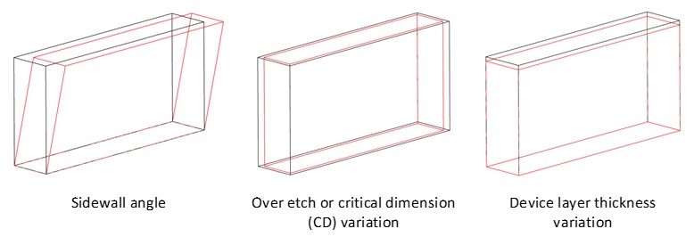
We created analytic equations to enable the calculation of electrostatic forces and actuator capacitances based on the distance between elements in the model, using COMSOL’s general extrusion operator. Such an approach is scalable to complex devices with many combs. We used COMSOL’s deformed geometry interface to simulate accurately the effect of manufacturing defects on the geometry. This feature enables a distortion of the mesh according to user-defined equations; the modified geometry is then used in the structural finite element simulation. With this feature the designer can cycle through design variations using the same mesh and consequently can obtain information on the effect of the design variations even when changes in the performance might be difficult to resolve with the mesh. Figure 1 illustrates some of the design variations that we implemented. Note that this approach allows combinations of these effects and/or functional variations across the device itself.
For the purposes of illustration, we developed a gyroscope model based on one of the first successful MEMS gyroscopes from Draper Laboratories in Cambridge, Massachusetts [1]. While this device is much smaller and simpler than many modern designs, it demonstrates the modeling techniques that we have developed to support MEMS designers.
The effect of manufacturing tolerances on design performance is significant. This simple gyroscope has comb drives configured to drive an in-plane mode, as illustrated in Figure 2 (a). The Coriolis forces acting on this mode excite an out-of-plane mode shown in Figure 2 (b), whose motion is detected by parallel plate capacitors below the proof masses.
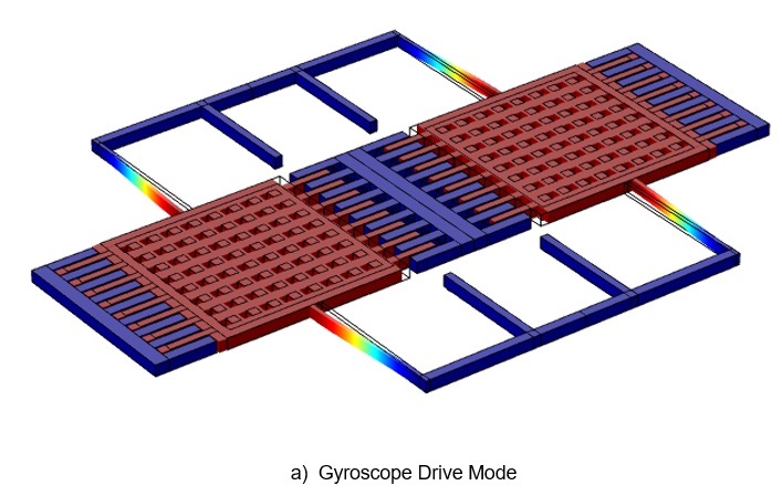
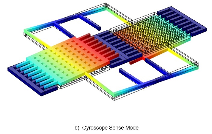
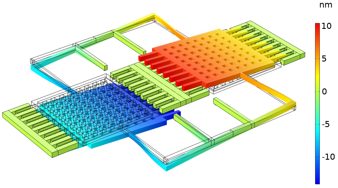
Figure 3 shows the effect of a 0.5° sidewall angle on the motion of the two proof masses in the absence of rotation – the vertical displacement is exaggerated by 1000 times in this visualization. The gyroscope response now contains significant out-of-plane motion due to the sidewall in the beam. This quadrature response is still almost 90° out of phase with the signal due to the sense mode, because the Coriolis force is proportional to velocity. Its magnitude corresponds to a rotation rate of 45,000 deg/s. Even the in-phase part of the drive signal, which is significantly less, corresponds to 3,900 deg/s. In a real gyroscope of similar design, a phase locked loop is used to consider the signal only in phase with the sense mode (in reality the Coriolis mode is not 90° out of phase with the drive, because of the finite mode separation). Even with such a system the challenge presented by manufacturing induced quadrature is significant.
The tools created by Veryst to model quickly different manufacturing variations enables designers to obtain quickly an accurate sense of the effect of manufacturing variations on the system.
For another example of Veryst’s capabilities in this area, see our Modeling a MEMS Lidar Mirror case study.
This case study was developed as part of a collaboration with COMSOL. The models created as part of this study will be available in COMSOL Multiphysics version 5.6 as the model library examples: “A Micromachined Comb-Drive Tuning Fork Rate Gyroscope” and “Manufacturing Variation Effects in a Micromachined Comb-Drive Tuning Fork Rate Gyroscope.”
1. J. Bernstein, S. Cho, A. T. King, A. Kourepenis, P. Maciel and M. Weinberg, "A micromachined comb-drive tuning fork rate gyroscope," [1993] Proceedings IEEE Micro Electro Mechanical Systems, Fort Lauderdale, FL, USA, 1993, pp. 143-148.