Redox Flow Battery Simulation for Long-duration Energy Storage
Technical Challenge
Long-duration energy storage is critical to ensure reliable and sustained integration of intermittent wind and solar resources. Redox flow batteries (RFBs) offer numerous advantages, including decoupled energy and power, long service life, and safe, scalable design. Optimizing the performance of RFBs requires maximizing the allowable current drawn during discharge while minimizing the pressure drop required to pump electrolyte across the stack. Both factors depend sensitively on flow channel design and geometry. Simulation of RFBs can help reduce development time and cost, de-risk scale-up, guide optimal design, and accelerate commercialization.
Veryst Solution
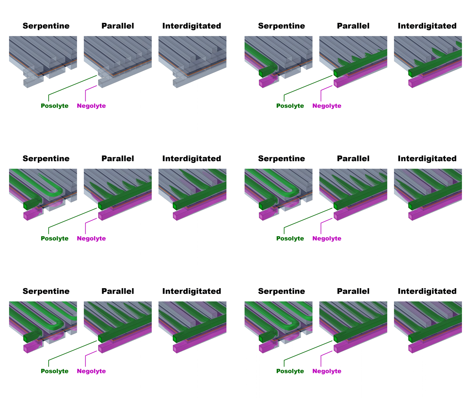
Veryst used COMSOL Multiphysics® to simulate the performance of three different flow channel designs to determine the impact of flow rate and current density on cell performance at room temperature. Serpentine, parallel, and interdigitated flow fields were simulated (Fig. 1) for a kW-scale cell (25 cm2 geometric area).
The three simulated flow configurations exhibit distinct velocity distributions (Fig. 2) that impact the cell pressure drop and mass-transfer-limiting current density (Fig. 3). The serpentine channels redirect flow across the porous electrodes, achieving good mass transfer (high limiting current density) at the expense of enhanced viscous dissipation (high pressure drop).
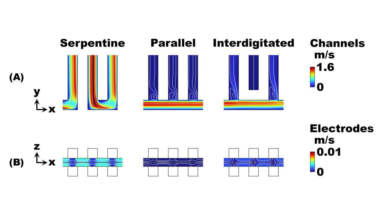
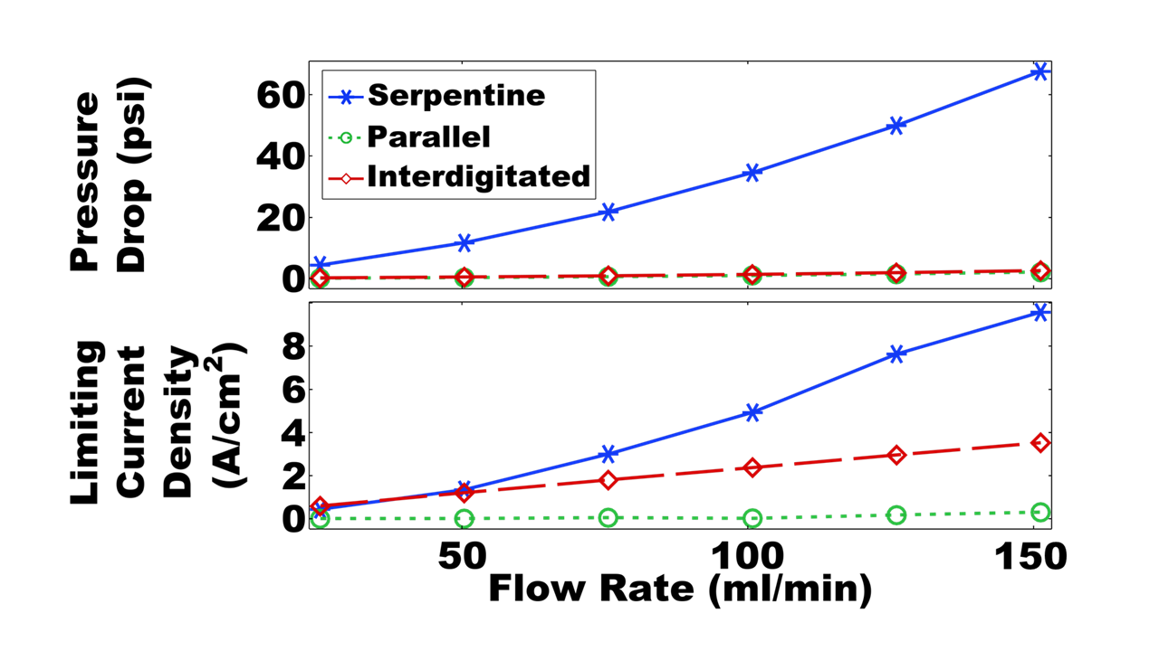
The parallel flow configuration mitigates viscous dissipation by dividing the flow across all 25 channels, thereby reducing the speed of the flow into each channel. However, at practical flow rates (>25 ml/min) the upstream channels are bypassed due to strong fluid inertia, resulting in uneven flow distribution and poor mass transfer. The interdigitated flow field achieves both low pressure drops and moderate limiting current densities by separating the inlet and outlet channels, forcing flow through the electrodes at relatively modest speed.
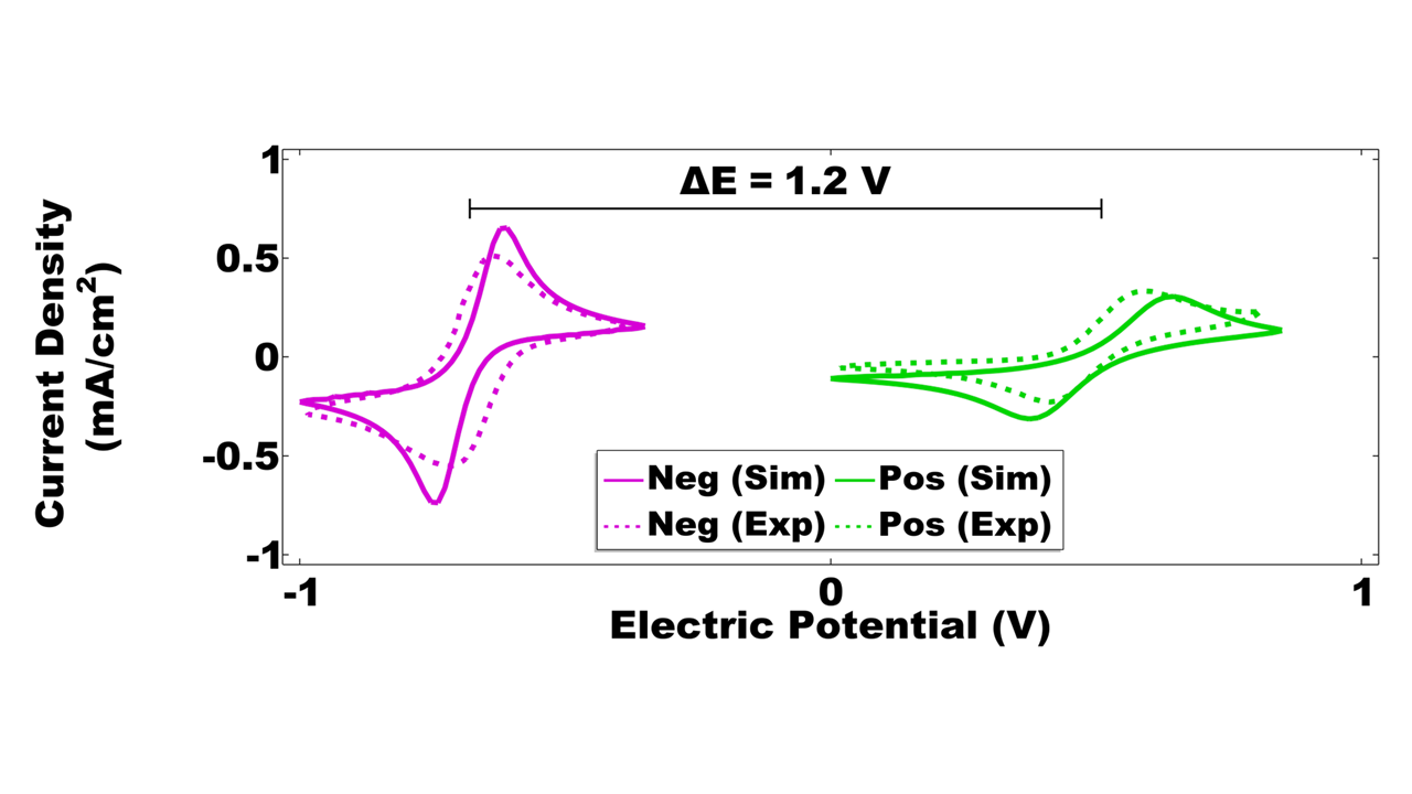
Multiphysics simulations of coupled fluid flow and electrochemistry in the porous electrodes were performed for the interdigitated flow cell to evaluate its polarization behavior during charge and discharge. Electrochemical kinetic parameters for an alkaline organic electrolyte chemistry were calibrated using cyclic voltammetry measurements from literature [1] (Fig. 4). These voltammograms predict an equilibrium cell potential of 1.2 V.
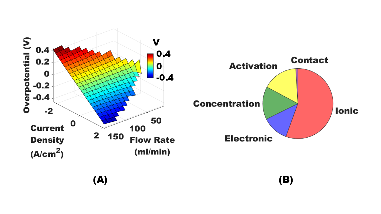
Cell overpotentials were simulated over a wide range of flow rates and current densities to map out the feasible operating space of the kW-scale RFB (Fig 5A). The partitioned channel design in the interdigitated flow cell enables control of the mass-transfer-limiting current density by varying the flow rate. Our simulations enable direct computation and comparison of the various voltage losses in the cell (Fig 5B), which limit the cell’s performance. These losses are due to ohmic (ionic and electronic), mass-transfer (concentration), kinetic (activation), and contact resistances.
Conclusion
Veryst’s simulations highlighted the performance tradeoffs among three different flow configurations for a kW-scale redox flow battery (RFB) cell. The interdigitated flow cell design achieves the optimal balance between flow resistance and mass transfer. Cell polarization is primarily limited by ionic conduction in the electrolyte. Simulations such as these can help accelerate timetables for RFB development and commercialization.
References
[1] K. Lin et al., Science 349.6255 (2015): 1529-1532