Technical Challenge
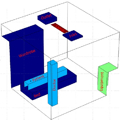
Efficient ventilation can reduce a building’s energy consumption and minimize airborne pathogen transmission in hospital rooms. In this problem we investigate ventilation in a hospital room containing a patient, a doctor, a bed, a wardrobe, a lamp, medical equipment, an inlet, and an outlet. We account for both forced ventilation and natural heat-induced convection, as well as the flow of suspended particles originating from a coughing patient. Layout of the room is shown in Figure 1. Ventilation rate is 6 ACH (air change per hour) for health care facilities, per ASHRAE Standard 170.
Veryst Solution
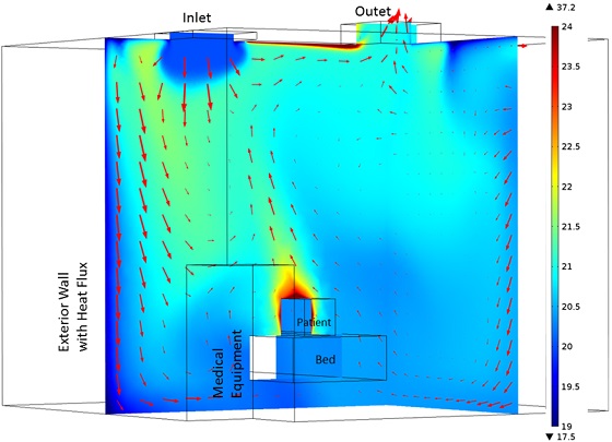
Veryst used CFD (computational fluid dynamics) to simulate ventilation in the hospital room, heat-induced natural convection, and the dispersion of suspended particles. Figures 2a and 2b show temperature distributions and velocity vectors adjacent to the doctor and patient. Average temperature of the room is measured at 21°C. Upward air movement next to the doctor and patient is seen in Figures 2a and 2b, which is due to natural convection. There is also a flow of air from the patient toward the doctor.
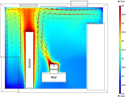
We calculated Predicted Mean Vote (PMV)(1) and Predicted Percentage of Dissatisfied (PPD)(2) based on ASHRAE Standard 55-2013. The average air temperature and air speed experienced by the patient is 20.8°C and 0.06 meters/second, respectively. The metabolic rate of a patient who is sleeping is considered 1 Met(3). We assumed that the patient is wearing trousers and a long-sleeve shirt and therefore his clothing level is 0.61 clo(4). If humidity is 50%, then PMV is -1.59 and PPD is 56%.
In that case, the probability of the patient being dissatisfied with the room temperature is 56%, with the sensation of being cool.
We also simulated the release of particle dispersion due to patient coughing. Coughing characteristics were obtained from “Flow dynamics and characterization of a cough” by JJ. K. Gupta et al. (2009). The animations below show the release of air due to coughing. All air exiting through the outlet is assumed to be subsequently particle free, as is inlet air.
Animations 3a, 3b. Particle tracing showing the motion of particles resulting from patient coughing. Particle color corresponds to velocity (m/s)
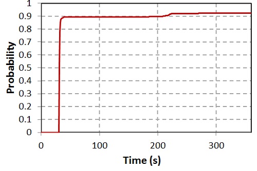
Figure 4 shows transmission probability of particles at the room ventilation outlet. None of the particles leave the room in 30 seconds after coughing. After three minutes, 8% of the particles still remain in the room.
___________________________
1 The average thermal sensation response of a large number of subjects using ASHRAE thermal sensation scale
2 Quantitative measure of the thermal comfort of a group of people at a particular thermal environment
3 Physiological measure expressing the energy cost of physical activities
4 Unit to measure insulation of clothes