Technical Challenge
Microfluidic devices are broadly used in diagnostic, genomic, biomedical, and pharmaceutical applications. Many of these applications require careful control of the concentration of chemical and biological species in the device. It is often important to remove reagents or samples from a previous processing step before continuing with the next step. This is achieved with a wash cycle, but the wash buffer volume and cycle time are typically constrained by cost, processing rate, and/or device design.
Furthermore, many applications have strict requirements on the maximum concentration of sample or reagent chemical remaining after a wash cycle, called chemical carryover or, simply, carryover. A detailed understanding of the fluid mechanics and mass transport in the microfluidic device is needed to design and optimize a wash cycle that satisfies these constraints and requirements. Simulations may be used to design a fast and effective wash cycle for any channel geometry.
Veryst Solution
To understand the effect of a wash cycle protocol on chemical carryover, Veryst developed COMSOL Multiphysics finite element models to simulate the coupled fluid mechanics and mass transport during a wash cycle in two microfluidic devices: one device with a straight channel and one with an L-shaped channel. Because the reagent concentrations are dilute, we used single-phase fluid flow and applied one-way coupling between the fluid mechanics and mass transport.
Furthermore, the Peclet number is large in all cases that we considered, leading to sharp concentration gradients during the wash cycle, which is accounted for in our model.
We first considered a straight channel initially filled with chemical at a certain concentration and then flushed with wash buffer (Figure 1). The wash cycle caused vertical and horizontal concentration gradients, the former of which equilibrated relatively quickly.
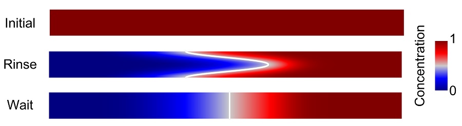
Figure 1. Microfluidic channel is initially filled with a chemical sample or reagent (top). Wash buffer is introduced at the left inlet, flushing out the chemical and creating a vertically and horizontally varying chemical concentration (middle). Vertical concentration gradients equilibrated after a few seconds of chemical diffusion (bottom). Channel dimensions are 7 cm long, 0.1 mm high, and 1 mm deep (into page). Only the central portion of the channel is shown in the figure.
We computed the maximum concentration in the device to quantify the amount of sample remaining after a wash cycle, shown in Figure 2 as contours depending on operating time and wash buffer volume per unit channel width (in this simulation into the page). The operating time is the wash cycle time plus a wait time, which we take as the diffusion time of (channel height)2/(10×(chemical molecular diffusivity)) = 1 s.
Contours such as these may be used to choose the wash cycle time and wash buffer volume required to reduce the maximum carryover concentration below a specified threshold.
Furthermore, the contours provide a quantitative relationship between the wash cycle time and wash buffer volume for a given carryover threshold concentration and may therefore be used to optimize the wash cycle for a given set of constraints (e.g., caps on wash buffer volume or operating time).
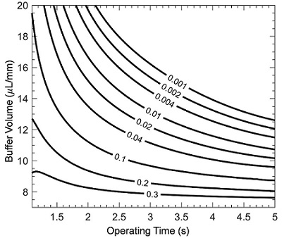
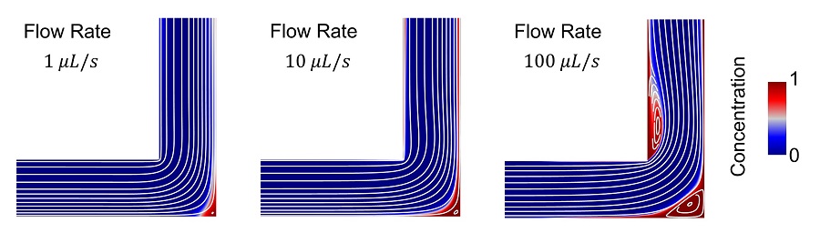
Figure 3. Carryover concentration relative to initial sample or reagent concentration (color) and flow field streamlines (white) for three different wash cycle protocols (corresponding to different flow rates, and therefore Reynolds numbers) in an L-shaped channel. Channel height 0.1 mm, depth (into page) 1 mm, length 0.6 mm. In each case, the same buffer volume is pumped through the channel. Recirculation zones develop and increase in size as the flow rate and Reynolds number increase.
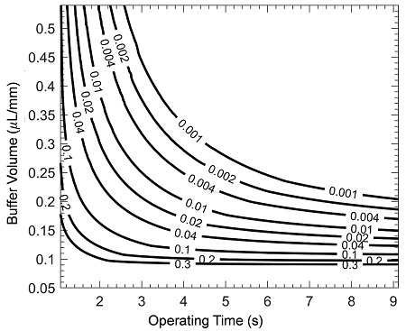
We considered carryover in a shorter L-shaped channel to illustrate the effect of a corner (see Figure 3). In an L-shaped channel, streamlines depend on operating time and wash buffer volume. Contours of the maximum carryover concentration (Figure 4) were qualitatively similar to the straight channel (Figure 2), but longer wash cycle times and larger wash buffer volumes (relative to the channel volume) were required to reduce carryover to an equivalent level (differences in volumes are due to the L-shaped channel having a smaller volume than the straight channel).
Another difference between the flow profiles in the L-shaped and straight channels are recirculation regions. A recirculation region occurs in the corner of the L-shaped channel, and that region grows as flow rate increases. For higher flow rates, a recirculation region also occurs on the inner side of the L-shaped channel, downstream of the corner. These recirculation regions reduce the efficacy of the wash cycle, and their presence and extent depend on the Reynolds number Re = channel height × velocity / viscosity. For Figure 3, Re = 1, 10, 100 from left to right. As Re increases, recirculation regions get larger and new ones may appear.
Conclusion
This study shows that the efficacy of wash cycles in reducing carryover concentration in microfluidic devices strongly depends on the wash protocol and channel geometry. A detailed understanding of the fluid mechanics and mass transport in a device coupled with accurate finite element simulations can help design and optimize effective wash cycle protocols.