Technical Challenge
Jamming can occur when particulates suspended in a viscous carrier fluid flow through confined geometries. Examples include the blockage of inkjet printer nozzles in additive manufacturing processes, the clogging in medical injection devices by protein aggregates, and the occlusion of pores by organic contaminants in water filtration membranes. Physically, jamming manifests when a lubricated, loosely packed suspension transitions to a frictional, granular state due to the interaction between large particulates and the containing surface.
This transition is accompanied by a sudden jump in the suspension viscosity—often called discontinuous shear thickening—and is highly dependent on the flow geometry, carrier fluid properties, and the size and shape of the suspended particulates. Predicting the conditions under which shear thickening and jamming occur in flow devices provides an operating window for stable, uninterrupted flow operation and critical design criteria to avoid device failure.
Veryst Solution
Veryst used computational fluid dynamics (CFD) with a phase transport and mixture model to simulate the flow of a particulate suspension through a narrow needle. The flow was generated by the plunger action of a syringe. The onset of jamming in the needle was evaluated as a function of the particle diameter and suspension volume fraction.
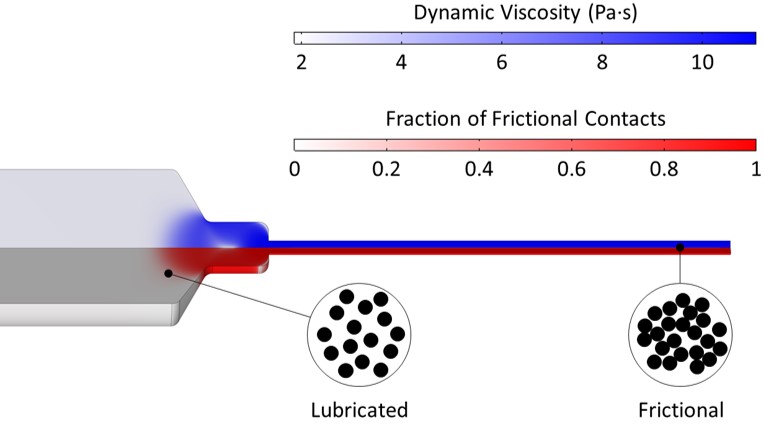
Figure 1 depicts the effective viscosity of the suspension in a cross-section of the syringe and needle.
Within the section of the syringe barrel where the viscosity is low, particles are separated by a lubricating layer of carrier fluid and the suspension flows smoothly. As the suspension approaches the throat of the needle, particles are forced into frictional contact and the viscosity rapidly increases. At sufficiently high particle volume fraction, a frictional network of particles spans the diameter of the needle and the suspension jams.
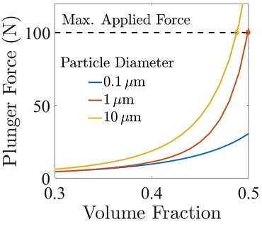
A useful metric for predicting the onset of jamming is the force that is applied to the plunger upstream of the needle to maintain a steady flow. Figure 2 shows the simulated plunger force as a function of the particle volume fraction for several particle diameters.
The particle volume fraction and particle diameters dramatically impact the viscosity of the suspension. Jamming occurs when the force required to push the suspension through the needle exceeds about 100 N—the typical maximum force exerted by a user’s thumb on a syringe plunger or in a flow-controlled syringe pumping system.
Figure 2 shows that the suspension exceeds this threshold of 100 N at different volume fractions for different particle sizes, and that for small particles, jamming does not occur. Larger particles jam more easily, while smaller particles flow freely through the needle without jamming.
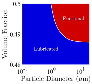
The threshold for jamming shown in Figure 2 enables the construction of an operating diagram for continuous flow through a narrow needle, plotted in Figure 3. Below a critical volume fraction (corresponding to 100 N of force), the suspension is well lubricated and flows continuously through the needle. Above this volume fraction, the majority of particle contacts are frictional and the suspension jams. This jamming volume fraction decreases as the particle diameter is increased. Jamming can, therefore, be avoided using smaller particles (though formulation design may require larger particles) or lower volume fractions.
Conclusion
Veryst employed computational fluid dynamics (CFD) simulations to predict shear thickening and jamming of a particulate suspension through a syringe needle, focusing on the effect of particle diameter and volume fraction. Simulations such as these can help predict the conditions under which jamming may occur in flow systems, which ultimately leads to time, cost, and materials savings in practical applications.